Tube torch with a switch
A 10 cm torch made from a toilet roll tube, a white LED and a CR2032 coin cell: pressing a paperclip on the side closes the circuit and the LED shines through an aluminium reflector.
What they will learn
- That a circuit needs a closed path from one terminal of the battery to the other, and that a switch is just a piece of that path that opens and closes.
- That an LED has polarity: the long leg (anode, +) must go to the + of the battery or it won't light.
- Which materials are conductors (aluminium, steel paperclips) and which are insulators (tape, cardboard, paper).
- What a short circuit is and why aluminium foil can drain the battery in minutes if it touches both terminals.
- That a reflector (a shiny cone) concentrates the light forwards.
Prepare beforehand
- Print the templates at 100 % and check with the ruler that disc C measures 42 mm.
- Measure the inside diameter of your tube: if it isn't 42 mm, draw disc C to that size with a compass (it should fit snugly, with no play).
- Test each LED with the battery before the session (long leg on the «+» face of the battery, short leg on the other): discard any that don't light.
- Remove the protective plastic from new batteries if they have it and keep them out of reach of children under 6.
- For groups, pre-cut discs C and D and cones R.
Materials and tools
- White LED — 1 (+1 spare) buy
5 mm, high brightness, 3.0–3.3 V / 20 mA, long legs left uncut (the long one is +) - Coin cell — 1 buy
CR2032 lithium, 3 V, 220 mAh, Ø 20 × 3.2 mm - Cardboard tube — 1
toilet roll tube, ≈ 100 mm long and Ø 42–45 mm - Metal paperclips — 2
standard 32 mm, bare steel with no plastic coating (coloured ones are plastic-coated: they don't conduct) - Aluminium foil — 1 piece, 30 × 30 cm
ordinary kitchen foil - Sticky tape — ≈ 70 cm
clear, 19 mm (insulating) - Corrugated cardboard — 1 piece, 10 × 5 cm
3 mm, for the head and the back cap - Card — 1 piece, 8 × 8 cm
160–200 gsm, for the reflector cone - Glue stick — 1
to stick the foil onto the card - Covering paper (optional) — 1 strip, 145 × 100 mm
A4 sheet printed with template E for decoration
Tools
- Scissors — cutting out templates, card and foil
- Awl or sharp pencil — making the 5 mm hole in the head and the 6 mm hole in the side of the tube adult
- Craft knife and cutting mat — cutting out the corrugated cardboard disc adult
- Ruler — measuring the positions on the tube and the strips
- Needle-nose pliers (optional) — bending the LED legs and opening out the lever clip
Pieces and templates
- C · Head (holds the LED) ×1 — 3 mm corrugated cardboard
- R · Reflector cone ×1 — 160–200 gsm card covered with foil on the inner face
- D · Back cap ×1 — 3 mm corrugated cardboard
- E · Decorative cover and drilling guide ×1 — 80 gsm paper
- F · Aluminium conductor strips ×2 — folded aluminium foil
Step by step
Test the LED
Slip the CR2032 between the two legs of the LED: the long leg on the large face with the «+» stamped on it and the short one on the other face. Squeeze with your fingers: the LED should light up.
1 The long leg is +: it goes on the battery face marked «+» 2 Press the legs against the battery: the LED should light up Check: If it doesn't light, turn the battery over. If it still doesn't light, try another LED.Tip: Remember: long leg = plus (+). If the legs have already been cut, the one on the flat side of the LED's base is the negative.Prepare the head adult
Cut out disc C (Ø 42 mm) and pierce its centre with an awl until the hole measures 5 mm. Push the LED in from behind until its base stops it: the bulb sits at the front and the legs at the back.
1 Cut out the 42 mm disc C along the red line 2 Pierce the centre with the awl until the hole measures 5 mm 3 Push the LED in from behind until the rim stops it Check: The LED stays firmly in place and straight without glue.Insulate the battery edge adult
Wrap one turn of sticky tape round the edge of the battery (the round rim), leaving both flat faces clear. The edge is part of the + terminal, and this way the strip from the − terminal won't touch it.
1 Wrap one turn of tape round the edge of the battery 2 Trim off the excess: both flat faces are left bare Tip: Trim any tape that sticks out with scissors so it doesn't cover the faces.Fix the long leg to +
First bend the LED's short leg outwards, at a right angle 3 mm behind the head: if it stays straight, it will hit the battery. Then bend the long leg at a right angle 5 mm behind the head, in the opposite direction, and lay it flat on the «+» face of the battery. Hold it in place with 2 pieces of tape in a cross, pressing firmly.
1 First bend the short leg outwards, 3 mm behind the disc 2 Bend the long leg at a right angle 5 mm behind the disc 3 Tape the long leg to the + face with two crossed strips: the LED stays off Check: The battery hangs from the long leg, behind the head; the short leg points the other way without touching the battery, and the LED does NOT light yet.Make the conductor strips
Cut two bands of foil 30 × 120 mm and fold each one lengthwise three times until you have a strip about 4 mm wide. These are pieces F.
1 Cut two bands of foil 30 × 120 mm 2 Fold it lengthwise three times, always in half 3 Flatten them with a fingernail: two F strips, 4 × 120 mm Connect strip A to the − terminal
Lay 15 mm of one F strip (strip A) on the centre of the «−» face of the battery and tape over it. The strip must come out on the side of the battery opposite the LED's short leg.
1 Stick 15 mm of strip A on the centre of the − face, with tape on top 2 Strip A comes out on the side opposite the short leg Check: Strip A only touches the «−» face: not the taped edge and not the long leg.Connect strip B to the short leg
The short leg already points outwards from step 4. Wrap 10 mm of the other F strip (strip B) tightly round its tip and cover the joint with tape, so no metal is left exposed. Then sheathe strip B: cut tape 1 cm wide (half a strip of tape) and fold it lengthwise over B, covering both sides, from the short leg until only its last 60 mm are left without tape. That way A and B can go through the same hole together without making contact.
1 Wrap 10 mm of B round the tip and cover the joint with tape 2 Sheathe B in tape except for its last 60 mm 3 Touch the ends of A and B: it lights; pull them apart: it goes off Check: Touch the end of strip A and the untaped tip of strip B together: the LED should light up. Let go: it goes off.Make the reflector
Stick foil onto an 8 × 8 cm piece of card with a glue stick, shiny side showing. Stick template R onto the other side and cut it out. Roll it into a cone with the foil on the inside and tape the 10° flap on the outside.
1 Stick foil onto the card with the shiny side showing 2 Stick template R on the back and cut it out 3 Roll it with the foil inside and close the flap with tape Check: The cone's mouth measures 40 mm and the LED's bulb (5 mm) fits through the small 8 mm hole.Fit the reflector to the head
Place the cone in front of the head with the LED's bulb pushed through the small hole. Fix it to the disc with 3 small pieces of tape. The foil only touches the LED's plastic, never the legs, which are on the other side of the disc.
1 Push the LED's bulb through the small hole in the cone 2 Fix it to the disc with 3 small pieces of tape Pierce the tube adult
Wrap template E round the tube with the «FRONT» edge flush with the open end and stick it down. Pierce the marked circle (40 mm from the open end) with the awl and widen it to 6 mm by twisting a pencil in it.
1 Stick E with «FRONT» at the open end: the circle is at 40 mm 2 Pierce the circle with the awl, with the tube resting on a cork 3 Widen it to 6 mm by twisting a pencil Insert the light module
Feed both strips together through the 6 mm hole from the inside, working from the open end of the tube (as B is sheathed in tape, it doesn't matter if they rub), and push the head with the cone in until the disc is 28 mm from the open end and the cone is flush with it. Pull the strips so they aren't slack.
1 Feed the strips out through the hole from inside and push the head in 2 The disc sits at 28 mm and the cone is flush with the open end Check: The head sits straight without wobbling, and B's tape sheath shows outside the hole. If the head is loose, wrap one turn of tape round its edge.Fit the contact clip
Run strip B back from the hole along a line 10 mm to the right of the clip axis. Its tape sheath must reach 70 mm from the open end (if it falls short, add tape up to there): that way it is insulated under the lever. Turn it towards the axis and cut it at 90 mm: the section from 70 to 90 mm has no tape. Place the contact clip (it measures 32 mm) on top, from 68 to 100 mm, and tape it down only along its back half, from 85 to 100 mm.
1 Run B backwards 10 mm beside the axis, covered in tape 2 Place the contact clip on B and tape it only along its back half 3 The front half of the contact clip is left exposed, with no tape Check: Between 68 and 85 mm, the contact clip is left exposed, with no tape over it, resting on B's bare foil.Fit the lever clip
Stick strip A along the clip axis between 45 and 55 mm from the open end. Place the tail of the second clip on top (from 45 to 77 mm) and hold it with two turns of tape only between 45 and 55 mm. Bend the clip upwards so its tip sits 4–5 mm above the contact clip.
1 Lay A on the axis with the tail of the lever clip on top, taped 2 Bend the tip of the lever clip up, 4–5 mm above the contact 3 Press the tip: the LED lights; let go: it springs up and goes off Check: When you press the tip of the lever clip, it touches the contact and the LED lights; when you let go, the clip springs back up and the LED goes off.Close with the back cap
Cut out cap D (Ø 46 mm) and fix it to the back end with a 3 cm tape hinge on one side and a folded tape tab on the other, so you can open it and change the battery.
1 Cut out the 46 mm cap D 2 Attach it with a tape hinge and a tab to open it Test it in the dark
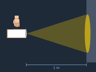
Turn off the light and aim at a wall 1 m away. Press the clip: you should see a circle of light about 30–40 cm across. Measure its diameter with and without the reflector cone.
1 In the dark, aim at a wall 1 m away and press the clip 2 Measure the circle of light with and without the reflector cone
Does it work? The test
In a dark room, aim the torch at a white wall 1 m away and press the lever clip 10 times in a row (on–off).
What should happen: The LED lights with every press without flickering and goes off when released. A bright patch of light ≈ 30–40 cm across appears on the wall. With the switch released, the LED must be completely off (if it glows faintly, there is a partial contact).
If something goes wrong
- The LED doesn't light when pressed — LED the wrong way round, plastic-coated paperclip, or the strip isn't making contact with the clip. Solution: First test the battery directly on the legs (step 1). Use uncoated paperclips and make sure the strip lies under the clip, flattened and with no tape in between.
- The LED glows faintly without being pressed or won't go off — Strip B has lost its tape sheath and is touching strip A (they go through the hole together), or the short leg is touching the battery. Solution: Go over B's tape sheath along its whole length, from the short leg to 70 mm from the open end, and wrap the short leg in tape; it should point outwards, away from the battery.
- The battery gets hot or runs flat in minutes — Short circuit: the strip from the − terminal is touching the edge of the battery (+ terminal) or the reflector foil is touching the legs. Solution: Take the battery out straight away. Replace the tape on the edge and check that the reflector cone is in front of the disc and isn't touching any metal.
- It works on and off — The foil strip has crumpled or torn at the hole in the tube. Solution: Make thicker strips (more folds) or use adhesive aluminium tape; reinforce the part that goes through the hole with tape.
- The lever clip doesn't spring back up — It is bent too far or the tape holds it too close to the tip. Solution: Tape only the 10 mm of the tail and bend the tip back up 4–5 mm.
- The light is very scattered — The LED is pushed in too far or sticks out too far relative to the cone. Solution: The LED's bulb should poke 3–5 mm into the cone, no more.
Safety
- Coin cells: if a child swallows one, it can burn their oesophagus within 2 hours. Keep them out of reach of children under 6 and, if you have any suspicion, go to A&E immediately.
- Never connect the two faces of the battery with foil or a paperclip: the short circuit heats it up and drains it.
- Don't stare at the LED up close or point it at anyone's eyes: high-brightness white LEDs are dazzling.
- Only an adult uses the awl, resting the disc or tube on a rubber or a piece of cork.
- Used batteries go in the battery recycling bin, not in the rubbish.
The science behind it
For children
The battery is like a water tank at the top of a mountain: electricity wants to flow down from the + side to the − side, but it can only travel along a metal path. That path goes through the LED, which lights up when electricity passes through it. The paperclip is like a drawbridge: when you press it, the bridge comes down and electricity crosses; when you let go, the bridge goes up and the light goes off. The shiny cone is a mirror that catches the light escaping to the sides and sends it forwards.
For the adult
A CR2032 (lithium–manganese dioxide) gives 3.0–3.2 V with no load and has an internal resistance of ≈ 10–20 Ω. A white LED (blue InGaN chip + yellow phosphor) starts to conduct at ≈ 2.7–2.9 V and needs ≈ 3.1–3.3 V at 20 mA; with the coin cell the current limits itself to ≈ 10–20 mA because of the internal resistance, which is why no resistor is needed (with 2 AA batteries, whose internal resistance is very low, one is needed: R = (V_batteries − V_LED)/I; for a red LED, (3.0 − 2.0)/0.01 = 100 Ω; for a white one the margin is so small that 22 Ω is enough as protection). The LED is a diode: it only conducts from anode (long leg) to cathode. With 220 mAh and an average of ≈ 15 mA, it lasts ≈ 10–15 h, getting gradually dimmer as the voltage drops. The switch is a normally open push button: the steel paperclip, thanks to its springiness, returns to the open position when released. Aluminium (resistivity 2.7·10⁻⁸ Ω·m) is a very good conductor; a strip 4 mm × 8 layers × 120 mm has negligible resistance (< 0.05 Ω), but that same conductivity is what causes short circuits if it isn't insulated. The reflector cone redirects forwards the light that the LED emits at wide angles (a 5 mm LED emits in a cone of ≈ 20–30°, with a wider halo), concentrating the beam.
- circuit: a closed path along which electricity travels from one terminal of the battery to the other.
- switch: a part that opens or closes the path of the current.
- LED: light-emitting diode: a tiny light that only works if you connect it the right way round.
- polarity: the + side and the − side of a battery or an LED.
- short circuit: a shortcut by which the current goes back to the battery without passing through the LED; it drains and heats the battery.
- reflector: a shiny surface that bounces light to direct it.
By age
- 5–7 years: The adult makes the light module (steps 2–7) and pierces the tube. The child tests the LED with the battery (step 1), makes the reflector, fits the clips and decorates the cover. Focus on «closed path = light».
- 8–10 years: They follow all the steps; the adult does the piercing and checks the insulation on the battery edge before closing up. Have them make the conductor detector.
- 11–12 years: Have them draw the circuit diagram with symbols, measure the battery life with a brightness graph and design a version with 2 AA batteries and a calculated resistor.
In a group or in class
Pairs, one torch per child (≈ €1 for LED and battery). Beforehand: test all the LEDs, pre-cut discs C and D and cones R, and cut the foil bands. 60 min: 10 min demonstration with an open and a closed circuit, 40 min assembly and 10 min «dark room» to compare beams on the wall. Hand out the batteries one at a time and collect any spares at the end. Have 3–4 spare LEDs and batteries.
Challenges
- Add a «stay on» mode: a rubber band that holds the lever clip down when you slide it over it.
- Build a two-colour torch with a switch for each LED.
- Make a signalling torch and send a message in Morse code to the other side of the room.
- Design a better reflector (longer, a different angle) and prove with the patch on the wall that it concentrates the light more.