Three-light traffic light
A 25 cm traffic light with three LEDs (red, amber and green) powered by a coin cell. A paperclip selector on the base lights up one light at a time, just like a real traffic light.
What they will learn
- That an LED only lights up one way round: long leg (anode) to the + and short leg (cathode) to the −.
- What a parallel circuit with a selector is: all the LEDs share the −, and the paperclip chooses which one gets the +.
- That two copper tracks touching each other make a short circuit and nothing lights up.
- Why a coin cell doesn't need a resistor with an LED (its internal resistance limits the current) but AA batteries do.
- The sequence and meaning of a traffic light: green, amber, red.
Prepare beforehand
- Print the templates at 100 % and check the red 50 mm line in the header. The body (370 × 265 mm) doesn't fit on A4: draw it with a ruler or join two sheets.
- Test each LED with the cell: long leg against the + face (the one with the writing), short leg against the −. Put aside any that don't light.
- Strip 15 mm off both ends of the 4 wires and label each one with tape: R (red), A (amber), V (green) and − (common).
- Cut about 20 strips of 5 mm copper tape: the 198 mm common track, 3 short 25 mm strips, the 6 sections of the L-shaped tracks, 6 little 10 mm pieces to cover the legs and 4 of 15 mm for the wires. The measurements of each track are on template A.
- Keep a spare cell to hand: if there's a long short circuit, the CR2032 runs flat.
Materials and tools
- 5 mm LEDs — 3 (red, amber/yellow, green) buy
diffused (coloured casing), 2–3.2 V, 20 mA; a "yellow-green" LED shines brighter on 3 V than a pure green one - CR2032 coin cell — 1 buy
3 V, lithium - CR2032 battery holder with wires — 1 buy
with red (+) and black (−) wires, ideally with a switch - Copper tape — 1 m buy
5–6 mm wide, ideally with conductive adhesive - Thin insulated wire — 4 lengths of 20 cm
0.2–0.5 mm², in 4 colours if possible (or mark them with coloured tape) - Metal split pins — 4
8–10 mm head, unvarnished, 15–20 mm legs - Metal paperclip — 1
32 mm, not plastic-coated - Corrugated cardboard — 1 sheet, 40 × 45 cm
3 mm (delivery box), for the body, the lid and the base - Black card — 1 A4 sheet
180–250 gsm, for the front panel and the visors - PVA glue or hot glue gun — 1
to close the box and stick it to the base - Clear sticky tape — 1 roll
to hold the copper joints and the wires in place
Tools
- Craft knife, metal ruler and cutting mat — cutting the body net and the base adult
- Scissors — cutting card, copper tape and visors
- Sharp pencil or awl — making the 5 mm LED holes and the 3 mm split pin holes adult
- Empty ballpoint pen — scoring the folds
- Scissors or wire strippers — stripping 15 mm off the wires adult
- Glue stick — sticking templates and the front panel
Pieces and templates
- A · Traffic light body (net, seen from the INSIDE) ×1 — corrugated cardboard 3 mm
- B · Top lid ×1 — corrugated cardboard 3 mm
- C · Base with selector ×1 — corrugated cardboard 3 mm
- D · Black front panel ×1 — black card
- E · Visor ×3 — black card
- F · Wires ×4 — thin insulated wire
Step by step
Test the LEDs
Touch the + face of the cell (the one with the writing) with the long leg of each LED and the − face with the short leg. Each LED should light up. If you put it the wrong way round it doesn't light, but it isn't damaged.
1 Find the + face of the cell and the long leg of the LED 2 Pinch the cell: long leg on the + face, short leg on the − 3 All 3 LEDs should light; the wrong way round they don't, but don't break Check: All 3 LEDs light up; put aside any that don't.Draw and cut out the body adult
Draw net A (370 × 265 mm) on the cardboard with the corrugations running vertically and stick the template on the face that will be on the inside. Cut round the outline with a craft knife and ruler, including the 20 × 8 mm notch. Score the folds with an empty ballpoint pen, without folding yet.
1 Draw A at 370 × 265 mm with the cardboard corrugations vertical 2 Cut round the outline with a craft knife, including the 20 × 8 mm notch 3 Score the folds with an empty ballpoint and don't fold yet Pierce the holes adult
Rest the cardboard on a large eraser or a piece of cork and pierce the 3 holes of 5 mm in the front face with a sharp pencil, twisting it until the LED casing fits through.
1 Find the 3 holes: 45 mm from the top and every 80 mm 2 On an eraser, twist the pencil until you open a 5 mm hole 3 The LED goes in from the inside up to its rim and pokes out Check: The LED goes in from the inside up to its rim and the dome pokes out the front.Stick on the black front panel
Pierce the 3 holes in front panel D and cut the same 20 × 8 mm notch in its bottom edge as the body has. Stick it to the outside of the front face with a glue stick, pushing a pencil through each hole to line the two up, with the notches matching. Also stick on the three visors E, 22 mm above each hole.
1 Pierce the 3 holes in D (and cut its 20 × 8 mm notch) 2 Stick D on the outside; a pencil through each hole lines them up 3 Stick a visor E 22 mm above each hole Fit the LEDs
With the cardboard flat and the inner face towards you, push each LED into its hole from the inside: red at the top, amber in the middle, green at the bottom. Turn each one so the LONG leg is on the right and the short one on the left, and bend the legs flat out to the sides.
1 Push each LED in from the inside: red at top, amber, green at bottom 2 Turn the LED with the long leg on the right and bend the legs flat 3 Looking from the inside, the 3 long legs point to R, A and V Check: Looking from the inside, the 3 long legs point to the right (towards the letters R, A, V).Stick on the common track
Stick a 198 mm strip of copper tape along the "−" line (vertical, to the left of the LEDs, from 40 to 238 mm from the top) and three short 25 mm strips from that track to each short leg. Each short strip starts on the left edge of the long track, so it overlaps it by about 5 mm: rub them down with your fingernail.
1 Stick 198 mm of copper along the − line, to the left of the LEDs 2 Stick three 25 mm strips from the − track to each short leg 3 Overlap the long track by 5 mm and rub hard with your fingernail Stick on the track for each light
Stick on the three L-shaped tracks following the template: R (29 mm horizontal section + 193 mm vertical), A (19 + 113 mm) and V (9 + 33 mm). Leave at least 4 mm between tracks: none should touch another.
1 Stick on the Ls: R (29 + 193 mm), A (19 + 113) and V (9 + 33) 2 Leave 4 mm or more between tracks: none touches the next one 3 If a strip touches another track, cut off the extra copper Check: No track touches the one next to it. If they touch, cut off the extra copper with scissors.Join the legs to the copper
Press each leg flat onto its track (short on the common one, long on its L) and trim off the spare leg. Watch out for the green LED's long leg: its horizontal section is only 9 mm and track A is 10 mm further on, so cut it about 10 mm from the LED, just over track V; the amber one at about 20 mm. Cover each leg with a little 10 mm piece of copper tape, rubbing hard, and cover each joint with clear sticky tape.
1 Press each leg onto its track: short to −, long to its L 2 Trim off the spare: the leg mustn't touch another track 3 Cover each leg with 10 mm of copper and clear tape on top Check: No leg crosses over a track that isn't its own (check the green one especially).Tip: If your copper tape doesn't have conductive adhesive, fold the end of the top strip back on itself so copper touches copper.Connect the wires
Lay the bare copper of each wire on the end of its track (at 238 mm, next to the notch), cover it with 15 mm of copper tape and sticky tape on top. The − wire to the common track, R, A and V to their own. Bring the 4 wires out through the notch.
1 Lay the bare copper of each wire on the end of its track 2 Cover it with 15 mm of copper tape and clear tape on top 3 Bring the 4 wires out through the notch at the bottom Test before closing
Touch the − face of the cell with the − wire and the + face with wire R: only the red should light. Repeat with A and V. Fix any fault now, while it's still easy.
1 − wire to the − face, R wire to the +: only the red lights 2 Repeat with A and V: each wire lights a single light Check: Each wire lights a single light and none lights two.Close the body
Fold the 4 vertical folds to 90° and glue the 10 mm tab inside the other side face. Fold the bottom tabs outwards. Glue lid B on top with its flaps on the outside.
1 Fold the 4 folds to 90° and glue the tab on the inside 2 Fold the bottom tabs outwards 3 Glue lid B on top, with the flaps on the outside Prepare the base adult
Cut base C (160 × 180 mm) and pierce the 4 holes of 3 mm. Wind the copper of wire R round the shank of a split pin and push it into hole R; do the same with A and V. Open the legs out underneath.
1 Cut base C (160 × 180 mm) and pierce the 4 holes of 3 mm 2 Wind the bare copper of wire R round the shank of the split pin 3 Push it into R and open the legs underneath; repeat with A and V Check: Each wire is trapped under the head of its split pin and doesn't come loose when you pull gently.Fit the pivot and the cell
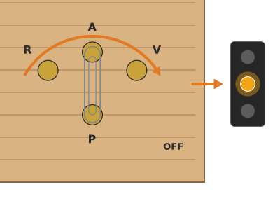
On split pin P hook the paperclip and wind on the red (+) wire of the battery holder; push it into its hole without tightening too much, so the paperclip can turn. Join the battery holder's black (−) wire to the − wire by twisting the copper together and cover it with tape. Glue the battery holder onto its rectangle.
1 On P hook the paperclip and wind on the holder's red (+) wire 2 Twist the black wire with the − wire and cover it with tape 3 Glue the battery holder on its rectangle; the paperclip should turn freely Glue the traffic light to the base
Stand the body up on the TRAFFIC LIGHT rectangle, with the front panel facing the selector, and glue the bottom tabs, folded outwards, with PVA or hot glue onto the 15 mm strip around the rectangle (not on top of it). Let the wires pass through the notch without squashing them.
1 Put glue around the TRAFFIC LIGHT rectangle, where the tabs go 2 Lower the body with the front panel facing the selector 3 Press it for a minute; the wires pass through the notch unsquashed Check: No tab sticks out over the base: the back one comes right up to the edge.Test the selector
Put the cell in the battery holder and turn the paperclip: on R the red lights, on A the amber, on V the green, and on OFF everything goes out. Practise the sequence green (10 s), amber (3 s), red (10 s).
1 Put the cell in the battery holder with the + face up 2 Turn the paperclip: R lights the red, A the amber, V the green 3 Practise the sequence: green 10 s, amber 3 s, red 10 s Paint it
Paint the side faces, the back and the lid black with poster paint (the front panel is already black). You can paint a white stripe on the base. Leave to dry for 20 minutes.
1 Paint the sides, the back and the lid black 2 Leave to dry for 20 minutes before playing
Does it work? The test
With a new cell, turn the paperclip through the four positions. Then dim the room light and look at the traffic light from 3 m away.
What should happen: Each position lights a single LED and OFF turns them all off. Red and amber shine brightly; the green may look a little dimmer (it needs more voltage). The CR2032 cell gives several hours of continuous light.
If something goes wrong
- One LED doesn't light — LED the wrong way round or loose copper joint. Solution: Check that the long leg goes to its R/A/V track. Go over the joint with another little piece of copper tape and rub hard.
- None of them light — Cell the wrong way round in the holder, flat cell or common track broken. Solution: Check the cell (the + towards the marked contact). Check that the − wire reaches the common track.
- Two lights come on at once — Two tracks are touching or the paperclip touches two split pins. Solution: Separate the tracks by cutting off the extra copper; shorten the paperclip or move the split pins further apart.
- The cell gets hot and nothing lights — Short circuit: the + touches the − directly. Solution: Take the cell out immediately. Look for copper from the common track touching a + wire.
- The green barely lights — Pure green LEDs need about 3 V, the limit of the CR2032. Solution: Use a new cell or a "yellow-green" LED (2.1 V). You can also use 2 AA batteries with a 100 Ω resistor.
- It flickers when you touch it — Loose copper joint or wire not properly trapped under the split pin. Solution: Press the split pin head down firmly and redo the joint that's failing.
Safety
- Coin cells are very dangerous if swallowed (they burn the oesophagus within 2 hours): keep them out of reach of children under 6 and use battery holders with a screw-down cover if there are young children around.
- If someone swallows a coin cell, go to A&E immediately.
- LED legs are sharp: bend them flat and cut them while holding the LED so the offcuts don't fly off.
- The craft knife and the awl are handled by an adult, with a cutting mat.
- Don't connect the LEDs to AA or 9 V batteries without a resistor: they burn out instantly.
The science behind it
For children
Electricity is like water that comes out of the + side of the cell and wants to get back to the − side. An LED is like a door that only opens one way: if you put it the wrong way round, the electricity can't get through and it doesn't light. The paperclip is like a traffic warden: it decides which way the electricity goes, and only the light on that path comes on. All the lights share the way back, which is the long copper track.
For the adult
An LED is a semiconductor diode: it conducts only when forward-biased (anode, the long leg, at the higher potential) and emits light whose colour depends on the material, which also sets its threshold voltage: ≈ 1.8–2.1 V for red and amber, 2.1 V for yellow-green and ≈ 3 V for pure green. Above the threshold the current rises very quickly, so it is normally limited with a resistor: R = (V_battery − V_LED) / I, for example (3 − 2) V / 0.01 A = 100 Ω with 2 AA batteries. The CR2032 has an internal resistance of 10–40 Ω that on its own limits the current to about 10–20 mA, which is why no resistor is needed here. The circuit is a common-cathode parallel circuit: the three LEDs share the − track, and a single-pole four-position switch (the paperclip: R, A, V and off) applies the + to one of them. Two tracks in contact form a short circuit (almost zero resistance) that drains the cell and leaves no voltage for the LED.
- LED: light-emitting diode: a tiny lamp that only lights if the current goes in through the long leg.
- polarity: which end is + and which is −.
- parallel: a connection in which each LED has its own path from the cell.
- selector: a switch that chooses between several paths.
- short circuit: a direct path from + to − that goes through nothing: the cell runs down and gets hot.
By age
- 5–7 years: The adult cuts the body, pierces it and sticks on the copper; the child fits the LEDs (long leg on the right), sticks on the front panel and the visors, and plays "green, amber, red" with the selector.
- 8–10 years: They do everything except the craft knife cuts. Let them test each LED with the cell themselves before and after sticking, and track down the fault if one doesn't light.
- 11–12 years: Have them draw the circuit diagram with symbols, work out the resistor needed with 2 AA batteries and add the pedestrian button or the buzzer.
In a group or in class
Pairs, one traffic light per pair. Before the session: cut and pierce the bodies, cut the copper strips and strip the wires; keep the coin cells put away and hand them out only at the end (small-parts control). 90 min session: 10 min of LED + cell in the hand, 60 min building, 20 min of "town", putting the traffic lights together in a model with paper streets. Collect all the cells at the end.
Challenges
- Make a junction with 2 traffic lights coordinated from a single selector.
- Add a pedestrian light with a red and a green figure drawn on tracing paper.
- Add a buzzer that sounds with the pedestrian green.
- Swap the bare LEDs for lenses: Ø 30 mm windows with tracing paper and the LED 10 mm behind.
- Design a cardboard rotary selector with a wheel instead of a paperclip.